


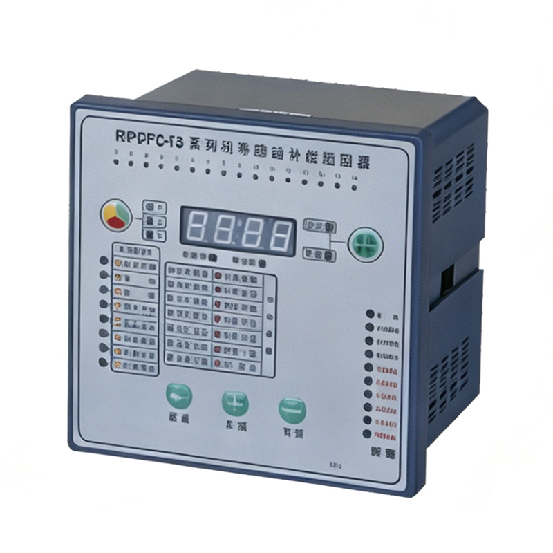
China LGRPCF3 Series Reactive Power Compensation Controller - Suppliers for Factory Automation Solutions
Technical Parameters
Compensation Solution (RPCF-12S for example)
| Compensation solution | Application | Switching method |
|---|---|---|
| 12-0 (three-phase compensation for all) | Power of three phases is basically balanced | According to total three-phase reactive power |
| 9-1 (three-phase compensation for 9 circuits and single-phase compensation for 1 circuit) | Little power difference among three phases | It switches to three-phase compensation capacitor according to the group with the smallest single-phase reactive power, and switches to single-phase compensation capacitor in case of inadequate or imbalanced reactive power |
| 6-2 (three-phase compensation for 6 circuits, and single-phase compensation for 1 circuit) | ||
| 3-3 (three-phase compensation for 9 circuits and single-phase compensation for 3 circuits) | ||
| 0-4 (splitting, four paths per phase) | Serious power imbalance among three phases | According to single-phase reactive power |
Relationship Between Compensation Scheme, Number of Output Channels and Output Terminals
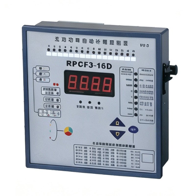
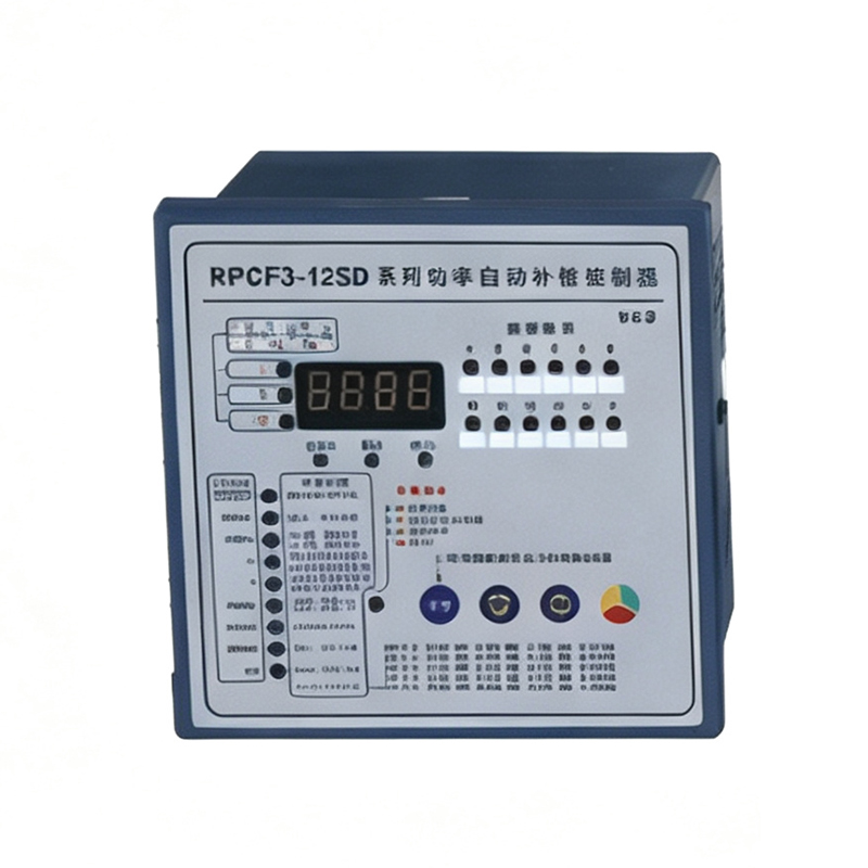
The LGRPCF3-12S controller has 12 outputs, numbered 1, 2, 3...12; the RPCF3-16 controller has 16 outputs, numbered 1, 2, 3...16. Under different compensation schemes and different output circuits, the RPCF3 will allocate the output control terminals in the following order: Phase A compensates for the first circuit, second circuit...; Phase B compensates for the first circuit, second circuit...; Phase C compensates for the first circuit, second circuit...; and the entire first circuit, second circuit... If the total number of channels set by the user is less than the maximum number of circuits supported by the hardware, the remaining terminals will be at the end (for reference, using the RPCF3-12S as an example, A: Phase A; B: Phase B; C: Phase C; G: Total supplement).
| Parameter setting value | Compensation plan: 6-2; Total number of compensation routes: 6; Number of sub-compensation routes: 2 | |||||||||||||
| Code of output terminal | 1 | 2 | 3 | 4 | 5 | 6 | 7 | 8 | 9 | 10 | 11 | 12 | ||
| Controlled phase | A1 | A2 | B1 | B2 | C1 | C2 | G1 | G2 | G3 | G4 | G5 | G6 | ||
| Parameter setting value | Compensation plan: 6-2; Total number of compensation routes: 6; Number of sub-compensation routes: 2 | |||||||||||||
| Code of output terminal | 1 | 2 | 3 | 4 | 5 | 6 | 7 | 8 | 9 | 10 | 11 | 12 | ||
| Controlled phase | A1 | B1 | C1 | G1 | G2 | G3 | G4 | G5 | null | null | null | null | ||
Frequently Asked Questions (FAQ)
The controller operates on a rated voltage of AC220V x 3 and supports an operating frequency range of 45-65Hz, with an undervoltage protection value set at AC180V.
It provides 0-9999Kvar measurement for reactive, active, and apparent power, with a sensitivity of 20mA and power factor display range from Lag 0.001 to Lead 0.001 via a 4-digit red LED display.
For minor power differences, schemes like 9-1, 6-2, or 3-3 are suitable. For severe three-phase power imbalance, scheme 0-4 (splitting, four paths per phase) is recommended for independent single-phase reactive power switching.
The controller allocates terminals in order: Phase A circuits (A1, A2...), Phase B circuits (B1, B2...), Phase C circuits (C1, C2...), followed by total three-phase supplement circuits (G1, G2...). Unused circuits are marked as null.
It supports embedded mounting with reverse tooth attachment or guide rail mounting. Available external dimensions are 144mm x 144mm (opening size 138mm x 138mm) or 122mm x 122mm (opening size 113mm x 113mm).